I. Introduction
Definition and Significance of Through-Wall Radar (TWR)
Through-Wall Radar (TWR) is a technology that allows for the detection and localization of objects or individuals through walls and other solid materials. Utilizing radio frequency (RF) signals, TWR systems can provide crucial information about the situation in obscured or enclosed areas without requiring physical entry.
The significance of TWR technology lies in its potential to save lives and improve operational outcomes in various critical scenarios. Some of the sectors where TWR has a notable impact include:
- Emergency response: In search and rescue operations, TWR can be employed to locate survivors trapped under rubble or within collapsed structures.
- Law enforcement and military: TWR systems can provide situational awareness during hostage scenarios, counter-terrorism operations, or other high-risk engagements by allowing personnel to view through walls and ascertain the positions of individuals inside a building.
- Industrial and construction: TWR can be used for detecting voids within structures, assessing the integrity of materials, or locating embedded objects such as pipes and wiring.
Applications of Through-Wall Radar
- Search and Rescue Operations:
- Locating trapped individuals in collapsed buildings
- Identifying safe pathways for rescuers through debris
- Law Enforcement:
- Hostage scenario management
- Surveillance and reconnaissance in urban operations
- Industrial Inspection:
- Detection of voids or defects within structures
- Locating embedded utilities
Radar Range Equation Specific to Through-Wall Radar
The radar range equation is a fundamental equation used in radar system design to predict the maximum range at which a radar can detect a target. The traditional radar range equation is given by:
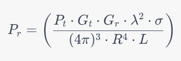
where:
- ( P_r ) is the received power,
- ( P_t ) is the transmitted power,
- ( G_t ) and ( G_r ) are the transmit and receive antenna gains,
- ( \lambda ) is the wavelength,
- ( \sigma ) is the radar cross-section of the target,
- ( R ) is the range to the target,
- ( L ) is the system loss factor.
In the case of TWR, the radar range equation must be modified to account for the attenuation caused by the wall material. The modified equation might look like this:
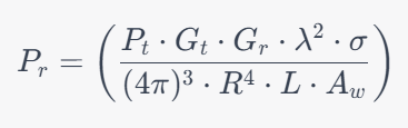
where:
- ( A_w ) is the attenuation factor of the wall material.
The attenuation factor ( A_w ) will depend on the properties of the wall material including its thickness, dielectric constant, and conductivity. This modification to the radar range equation helps to account for the additional challenges posed by wall penetration in through-wall radar applications.
The loss factor (L) in TWR will be a product of the usual radar loss factors and the additional loss due to the wall material, which can be represented as L=Lr⋅Lw, where Lr is the radar loss and Lw is the wall loss.
The wall loss Lw can be further detailed considering the type of material, its thickness, and its dielectric properties, among other factors.
This introduction sets the stage for a deeper exploration into the modeling, implementation, and performance analysis of TWR systems in the subsequent sections of your research paper.
II. Through-Wall Models
A. Description of the challenges posed by wall materials and thicknesses:
Walls, by their very nature, are barriers. When we talk about “through-wall” models, we often refer to the challenges associated with transmitting signals or waves through these barriers. Some of the primary challenges posed by wall materials and thicknesses include:
- Attenuation of Signals: Different wall materials absorb, reflect, or scatter signals to varying degrees. For instance, a concrete wall will typically attenuate radio frequency (RF) signals much more than a wooden wall.
- Reflection and Scattering: Walls can cause signals or waves to reflect or scatter. This can lead to issues such as multi-path interference where a signal reaches a receiver via multiple paths causing distortion or fading.
- Frequency Dependency: The effect a wall has on a signal often depends on the frequency of that signal. For instance, lower frequency signals might penetrate certain walls better than higher frequency ones.
- Wall Thickness: The thicker the wall, the greater the attenuation for most signals. A thick stone wall, for example, can be a significant barrier for many types of signals.
- Embedded Materials: Some walls might have metal rebar, mesh, or other materials embedded within them, which can introduce additional challenges for signal transmission.
- Variability and Inconsistency: Even if you know the material of a wall, there can be inconsistencies in its composition, density, and other factors that make predicting its effects more complex.
B. Overview of modeling approaches to address these challenges:
Modeling through-wall propagation is a complex task. Several approaches can be used:
- Ray-Tracing Models: These models consider the wall as a series of layers and calculate how a signal or wave would reflect, refract, and attenuate as it passes through each layer. This is particularly useful for high-frequency signals.
- Finite-Difference Time-Domain (FDTD) Method: This computational method breaks down space into a grid and calculates how electromagnetic waves propagate over time. It’s powerful for modeling complex environments but can be computationally intensive.
- Statistical Models: Instead of trying to model every detail of a wall’s impact on a signal, statistical models use empirical data to make predictions. For instance, they might use measurements taken in real-world environments to predict the average attenuation a signal might experience when passing through a specific type of wall.
- Hybrid Models: These models combine elements of deterministic (like ray-tracing or FDTD) and statistical models. They might use ray-tracing to model the main paths a signal takes, and then statistical methods to account for multi-path interference and other complex effects.
- Material Characterization: Some models focus on characterizing the materials within a wall. For instance, measuring the dielectric properties of a material at various frequencies can provide valuable data for predicting its impact on signals.
- Machine Learning and AI: With the growth of computational power and the availability of large datasets, machine learning approaches are being employed to predict through-wall behavior. These methods can be trained on large amounts of empirical data to make predictions in various scenarios.
In conclusion, the challenges posed by walls in terms of material and thickness are significant when it comes to signal propagation. However, a range of modeling approaches, from deterministic to statistical to machine learning-based, are available to address these challenges. The best approach often depends on the specific requirements of the application in question.
III. 1D Model for Simulating Range Profiles
A. Discussion of the principles behind 1D range profiling:
Range profiling is a technique used in radar and sonar systems to determine the distance (or range) to various objects or targets. The primary goal is to produce a profile that represents how the returned signal strength (or power) varies with distance. This is important in applications such as target detection, imaging, and environmental sensing. The “1D” in the term implies that the profiling is done along a single dimension, typically the line-of-sight from the radar or sonar system.
Principles:
- Time-Delay Measurement: At its core, 1D range profiling is about measuring the time delay between the transmission of a pulse and the receipt of its echo or reflection from an object. Since the speed of electromagnetic waves (for radar) or sound waves (for sonar) is known, this time delay can be translated into a distance or range.
- Pulse Compression: In modern systems, instead of sending a single, high-power pulse, a modulated pulse or waveform is sent. The received signal is then cross-correlated with the sent waveform to achieve pulse compression, enhancing the range resolution.
- Frequency Modulation: Some advanced radar systems use frequency-modulated continuous-wave (FMCW) signals. The difference in frequency between the transmitted and received signals provides range information.
- Resolution: The duration and shape of the transmitted pulse, along with the bandwidth of the system, determine the range resolution. A shorter pulse or a system with wider bandwidth typically provides better range resolution.
- Ambiguities: In real-world scenarios, multiple reflections can occur from multiple objects. The challenge lies in distinguishing between these reflections, especially when they are close together in range.
B. Overview of simulation methods and results:
Simulating 1D range profiles involves replicating the radar or sonar environment in a computational model to predict how real systems would behave.
- Method of Moments (MoM): This is a numerical technique used to solve the integral equations related to electromagnetic scattering. It’s particularly useful for simulating radar returns from complex objects.
- Finite-Difference Time-Domain (FDTD): This method, as mentioned earlier, is a computational approach to simulate electromagnetic wave propagation. It can be used to model how radar waves interact with various objects and environments.
- Fast Fourier Transform (FFT): After receiving echoed signals, FFT can be used to transform the time-domain data into the frequency domain, making it easier to interpret and analyze the range profile.
- Monte Carlo Simulations: These simulations involve running the model many times with different inputs to understand the variability and uncertainty in the results. For range profiling, this might mean simulating returns from various types of targets or under different environmental conditions.
Results:
- Clear Peaks: In simulated range profiles, clear peaks represent objects or targets. The distance to the peak from the start indicates the range to the object.
- Resolution: The ability of the simulated system to distinguish between two closely spaced objects can be observed in the results.
- Clutter and Noise: Simulations often introduce clutter (unwanted reflections, perhaps from the ground or sea surface) and noise (random interference or errors) to replicate real-world conditions. Effective range profiling systems should be able to distinguish targets from this clutter and noise.
In essence, 1D range profiling is about understanding the distance to various targets based on the time it takes for a transmitted signal to return after reflection. Simulations help in understanding and improving these systems by offering a controlled environment to test and optimize different parameters.
IV. 2D Models for Imaging
a. Simulating Rail Synthetic Aperture Radar (SAR) Imagery
- Explanation of SAR and its application in TWR:
Synthetic Aperture Radar (SAR) is a form of radar imaging system that uses the motion of the radar antenna over a target region to provide finer spatial resolution than conventional beam-scanning radars. Essentially, SAR produces high-resolution remote sensing imagery by synthesizing a large “virtual” antenna aperture, which is achieved as the radar moves.
Application in Through-Wall Radar (TWR): SAR techniques can be applied to TWR to improve the resolution and clarity of images of objects or individuals behind walls or other obstructions. The primary advantage is the ability to discern finer details in situations where walls or other materials might otherwise obscure or degrade the quality of radar returns.
- Description of the 2D model for Rail SAR and simulation results:
The 2D model for Rail SAR involves mounting the radar system on a rail or a linear track. As the radar moves along this track, it continuously collects data from a scene (e.g., a room behind a wall). The collected data over the rail’s length is then synthesized to produce a high-resolution image of the scene.
Simulation Results: Simulating Rail SAR can yield results that show improved resolution and target discernibility as compared to a stationary radar system. Targets that may overlap or be indistinct in conventional radar imagery might appear as distinct entities in SAR images. The quality of results often depends on factors like the radar’s wavelength, the wall material, and thickness, and the distance between the radar and the wall.
b. Switched or Multiple Input Multiple Output (MIMO) Arrays
- Explanation of MIMO technology and its relevance to TWR:
MIMO (Multiple Input, Multiple Output) refers to a technology where multiple antennas are used at both the transmitter and receiver to improve communication performance. It achieves this by spatial multiplexing (sending multiple data streams on the same frequency but on different spatial paths) and space-time coding (improving reliability and resilience to fading).
Relevance to TWR: In the context of Through-Wall Radar, MIMO can help improve the system’s ability to detect and localize targets behind walls. By leveraging multiple antennas, MIMO-TWR systems can provide a more comprehensive view of a scene and can better handle the reflections, scattering, and diffraction effects typical of through-wall environments.
- Discussion of the 2D model for switched or MIMO arrays and simulation results:
2D Model for MIMO Arrays: The 2D model might represent a grid or matrix of antennas, both on the transmitting and receiving ends. Each antenna or a subset of antennas can transmit signals, and the reflections from these signals received by multiple antennas can be used to reconstruct an image of the scene.
Simulation Results: In simulations, MIMO arrays typically demonstrate enhanced imaging capabilities as compared to single-input, single-output systems. This includes better target localization, improved resolution, and increased resilience to interference or noise. The ability to gather data from multiple spatial perspectives allows for more accurate reconstructions of the scene behind the wall.
In conclusion, both Rail SAR and MIMO arrays represent advanced methodologies in the realm of Through-Wall Imaging. They provide tools and techniques that enhance the capability of radar systems to see through obstructions with higher clarity and accuracy.
V. Examples of Through-Wall Imaging Systems
a. S-Band Range Gated FMCW Rail SAR
- Implementation details:
- Frequency: The S-band typically ranges from 2 to 4 GHz. For through-wall imaging, the frequency selected within this range needs to strike a balance between resolution (higher frequencies) and penetration depth (lower frequencies).
- FMCW (Frequency-Modulated Continuous Wave): This technique involves varying the transmitter frequency over time and then analyzing the received signal’s delay and frequency shift. This provides information about the target’s range.
- Range Gating: This technique allows for the isolation of signals returning from specific distances, enabling the system to focus on targets at certain depths.
- Rail SAR (Synthetic Aperture Radar): A radar system mounted on a rail or movable platform. As the radar moves, it captures data from multiple positions, synthesizing a “virtual” large aperture to improve the resolution.
- Expected performance and results:
- Resolution: Due to the SAR technique, this system can achieve higher spatial resolution than static systems.
- Depth Penetration: Operating in the S-band, the system can penetrate most common building materials to a reasonable depth, although performance can decrease with very thick or dense materials.
- Range Information: FMCW provides accurate range data, and when combined with range gating, allows for selective imaging of targets at different depths.
b. S-Band Switched Array
- Implementation details:
- Frequency: Operates in the S-band range (2 to 4 GHz).
- Switched Array: Rather than transmitting and receiving from all antennas simultaneously, the system switches between antennas. This provides multiple look angles, enhancing spatial resolution and aiding in clutter rejection.
- Expected performance and results:
- Resolution: Multiple look angles from the switched array can improve resolution and clutter discrimination.
- Depth Penetration: Similar to the FMCW Rail SAR, it can penetrate most common building materials, but performance varies based on material and thickness.
- Multiple Look Angles: This helps in resolving ambiguities in target positioning and identifying targets in cluttered environments.
c. Real-Time Through Wall Radar Imaging System
- Implementation details:
- Real-Time Processing: This system emphasizes processing data on-the-fly to provide immediate imaging results. This requires robust and fast computational capabilities.
- Frequency Range: The exact frequency can vary, but for through-wall applications, S-band or even lower frequencies (like UHF) might be used for better penetration.
- Antenna & Receiver Design: These components are optimized for both sensitivity (to detect weak signals) and selectivity (to reject unwanted signals).
- Expected performance and results:
- Immediate Feedback: As a real-time system, one of its primary advantages is providing immediate imaging feedback, essential for applications like search and rescue or tactical operations.
- Depth Penetration: Depending on the chosen frequency, this system should provide good penetration through common walls, although thicker and denser materials can still pose challenges.
- Resolution: The resolution might be a trade-off for real-time capabilities. However, advanced algorithms and high-speed processing can still offer reasonably detailed images.
In summary, the specific performance of any through-wall imaging system will depend on its design parameters and the challenges posed by the operational environment. The above systems highlight different strategies and technologies that can be employed in through-wall imaging, each with its advantages and trade-offs.
VI. Summary
Recap of Key Findings:
I. Introduction – Definition and Significance of Through-Wall Radar (TWR):
- Definition: TWR is a specialized radar technology designed to detect and localize objects or individuals through walls and other opaque solid materials, utilizing RF signals.
- Significance: The technology is invaluable across various sectors, aiding in life-saving search and rescue operations, enhancing situational awareness for law enforcement and military personnel, and providing critical insights in industrial and construction settings.
Applications of Through-Wall Radar:
- Search and Rescue Operations: TWR proves crucial in locating survivors in disaster-stricken areas, helping to map safe pathways through debris.
- Law Enforcement: In high-risk scenarios like hostage situations or urban surveillance, TWR offers a non-intrusive method to ascertain the positions and movements of individuals inside buildings.
- Industrial Inspection: The technology assists in assessing structural integrity, detecting voids, and locating embedded utilities within structures.
Radar Range Equation Specific to Through-Wall Radar:
- Modified Equation: The traditional radar range equation must be adjusted to account for the attenuation caused by walls, introducing an attenuation factor ( ��Aw ) that depends on the material’s properties.
- Loss Factors: The system loss factor ( �L ) in TWR is a product of standard radar losses and additional losses due to wall materials, requiring a comprehensive understanding of these elements for accurate system design and performance prediction.
II. Through-Wall Models
Through-wall models play a crucial role in understanding and overcoming the challenges associated with transmitting signals through walls. The primary issues stem from the attenuation of signals, reflection and scattering, frequency dependency, wall thickness, embedded materials, and variability in wall compositions. The described modeling approaches—ray-tracing models, Finite-Difference Time-Domain (FDTD) method, statistical models, hybrid models, material characterization, and machine learning/AI techniques—provide a spectrum of methods to predict and mitigate these challenges. Each approach has its strengths and is suitable for different scenarios, making them invaluable tools in the realm of through-wall radar (TWR) technology.
III. 1D Model for Simulating Range Profiles
In this section, we will recap the key findings from the previous discussion on 1D Model for Simulating Range Profiles, covering both the fundamental principles behind 1D range profiling and the simulation methods used to predict its performance.
A. Discussion of the principles behind 1D range profiling:
1D range profiling is centered around determining the distance to targets using radar or sonar by measuring the time delay of the returned signal. The technique relies on the principles of time-delay measurement, pulse compression, frequency modulation, and achieving a high resolution to distinguish closely spaced objects, while also managing and mitigating ambiguities arising from multiple reflections.
B. Overview of simulation methods and results:
To accurately predict the performance of 1D range profiling systems, various simulation methods are employed:
- Method of Moments (MoM): Used for solving complex electromagnetic scattering problems, helping to predict radar returns from various targets.
- Finite-Difference Time-Domain (FDTD): A versatile method for simulating wave propagation, providing insights into how waves interact with objects and the environment.
- Fast Fourier Transform (FFT): Used to transform time-domain data to the frequency domain, facilitating the analysis and interpretation of range profiles.
- Monte Carlo Simulations: A method for assessing variability and uncertainty in results, ensuring robust performance of range profiling systems under different conditions.
Results from these simulations typically manifest as:
- Clear Peaks: Indicating the presence and range of targets.
- Resolution: Highlighting the system’s ability to distinguish between closely spaced objects.
- Clutter and Noise: Providing a realistic scenario to test the system’s effectiveness in target detection amidst interference and errors.
In conclusion, 1D range profiling is a crucial technique in radar and sonar systems, with its effectiveness depending largely on the understanding and mitigation of challenges related to signal propagation, resolution, and ambiguities. Simulation plays a vital role in this, offering a controlled environment to study these factors, optimize system parameters, and ultimately, enhance the performance and reliability of range profiling systems.
IV. 2D Models for Imaging
a. Simulating Rail Synthetic Aperture Radar (SAR) Imagery
SAR and TWR:
Synthetic Aperture Radar (SAR) achieves high-resolution imagery by utilizing the movement of the radar system, creating a ‘virtual’ large aperture. When applied to Through-Wall Radar (TWR), SAR enhances the capability to capture detailed images through obstructions, providing clearer and more precise results than conventional radar systems.
2D Model for Rail SAR:
This model entails mounting the radar on a rail, allowing it to move linearly and capture data across a specified range. As the radar progresses along the rail, it accumulates data which is then synthesized to generate a high-resolution image of the hidden scene.
Simulation Results:
Simulations of Rail SAR reveal significant improvements in spatial resolution and target distinguishability, showcasing the system’s efficacy in identifying and separating objects or individuals even when obstructed by walls. The effectiveness is influenced by various factors including the radar’s frequency, the wall’s properties, and the radar-wall distance.
b. Switched or Multiple Input Multiple Output (MIMO) Arrays
MIMO Technology and TWR:
MIMO technology, with its multiple antennas at both transmitter and receiver ends, enhances communication performance through spatial multiplexing and space-time coding. In TWR, MIMO’s multiple antennas afford a more comprehensive and detailed view of the hidden scene, increasing the radar system’s resilience to common through-wall challenges like scattering and diffraction.
2D Model for MIMO Arrays:
In this model, antennas are arranged in a grid or matrix, with each playing a role in transmitting and receiving signals. The interaction of these signals, after reflecting off objects in the hidden scene, is utilized to reconstruct a detailed image of the environment.
Simulation Results:
MIMO arrays, in simulation, consistently outperform single-antenna systems, delivering enhanced imaging capabilities. This translates to more accurate target localization, improved resolution, and a heightened ability to overcome noise and interference. The array’s multiple vantage points provide a richer dataset, resulting in a more precise and reliable reconstruction of the scene beyond the wall.
Conclusion:
Both Rail SAR and MIMO arrays stand as advanced and powerful methodologies in the Through-Wall Imaging domain, each bringing unique strengths to the table. Rail SAR is exceptional in enhancing spatial resolution, while MIMO arrays excel in providing multiple perspectives for a more accurate scene reconstruction. These technologies collectively elevate the capabilities of radar systems in perceiving and interpreting scenes hidden behind obstructions.
V. Examples of Through-Wall Imaging Systems
a. S-Band Range Gated FMCW Rail SAR
- Key Implementation Details:
- Operates in the S-band (2-4 GHz), balancing resolution and penetration.
- Utilizes FMCW for range information.
- Employs range gating for focusing on specific depths.
- Uses Rail SAR for enhanced resolution through synthetic aperture.
- Expected Performance and Results:
- Achieves high spatial resolution due to SAR.
- Provides reasonable depth penetration, though performance can decrease with thicker/denser materials.
- Offers accurate range information and selective depth imaging.
b. S-Band Switched Array
- Key Implementation Details:
- Operates in the S-band range.
- Uses a switched array for multiple look angles.
- Expected Performance and Results:
- Enhances resolution and clutter discrimination.
- Penetrates common building materials, with performance dependent on material and thickness.
- Resolves target positioning ambiguities and identifies targets in clutter.
c. Real-Time Through Wall Radar Imaging System
- Key Implementation Details:
- Focuses on real-time processing for immediate results.
- Operates in S-band or lower frequencies for better penetration.
- Optimizes antenna and receiver for sensitivity and selectivity.
- Expected Performance and Results:
- Provides immediate imaging feedback, crucial for time-sensitive applications.
- Achieves good penetration through common walls, though challenges remain with thicker/denser materials.
- Balances resolution with real-time capabilities, leveraging advanced algorithms and high-speed processing.
Each of these systems demonstrates a different approach to through-wall imaging, tailored to specific operational needs and challenges. The S-Band Range Gated FMCW Rail SAR emphasizes high resolution and selective depth imaging; the S-Band Switched Array focuses on resolving target positioning in cluttered environments; and the Real-Time Through Wall Radar Imaging System provides immediate feedback for situations where time is of the essence.
B. Future Prospects and Research Directions in Through-Wall Radar (TWR) Technology
The advancement of Through-Wall Radar (TWR) technology holds promising prospects, driven by developments across computational models, material science, machine learning, and ethical considerations.
1. Enhanced Computational Models and Material Characterization:
- Computational Power and Sophistication: With increasing computational capabilities and the evolution of machine learning algorithms, we can anticipate more precise and efficient models for through-wall imaging, blending empirical data, physical laws, and advanced algorithms to enhance wall effect predictions.
- Understanding Materials: Delving deeper into the electromagnetic properties of various building materials across different frequencies is pivotal. This comprehensive material characterization would facilitate more accurate predictions regarding signal attenuation and scattering, subsequently boosting TWR system performance.
2. Integration and Technological Synergy:
- Combining Sensing Modalities: Integrating TWR technology with other sensors (acoustic, thermal imaging, etc.) promises the development of robust and versatile imaging systems, enhancing capability in navigating complex wall structures.
- Real-Time Processing and AI-Driven Insights: The advent of algorithms capable of real-time data processing, augmented by AI, is set to significantly enhance TWR applications, especially in scenarios demanding swift decision-making such as emergency response and military operations.
3. User Experience and Ethical Framework:
- Intuitive User Interfaces: Research aimed at improving how through-wall imaging results are conveyed could result in more user-friendly and informative interfaces, thereby making the technology more accessible and impactful in critical situations.
- Addressing Ethical and Privacy Concerns: As TWR technology continues on its upward trajectory, it is imperative to address the ethical and privacy considerations associated with its deployment, establishing clear guidelines and standards for responsible use.
4. Robustness, Portability, and Customization:
- Adaptability to Various Environments: Ensuring that TWR systems are resilient and effective across diverse conditions and settings, including variable wall materials and adverse weather conditions, is essential.
- Miniaturization for Enhanced Portability: Progress in miniaturizing TWR systems will enhance their portability and application scope, making them more versatile and user-friendly.
- Application-Specific Tailoring: Customizing TWR systems to meet the unique demands and constraints of specific applications (such as search and rescue, law enforcement, or military operations) will optimize their utility and effectiveness.
5. Driving Innovation and Ensuring Responsible Use:
- Continuous Technology Advancements: The ongoing push for innovation in signal processing, imaging capabilities, and materials science holds the key to unlocking the full potential of TWR technology.
- Balancing Progress with Ethical Standards: As we forge ahead, balancing technological progress with a steadfast commitment to ethical standards and privacy protection will be crucial to ensuring responsible and respectful use of TWR systems.
In conclusion, the future of TWR technology is intricately tied to advancements across multiple domains. From computational prowess and material science to ethical frameworks and application-specific innovations, a holistic and balanced approach is essential to navigate the complexities of through-wall radar systems, ensuring their evolution is both technologically advanced and ethically sound.
